DT overlays are piece of device tree source codes that enables addition of extra nodes to the live device tree of an embedded linux system. They allow additional hardware devices to become part of current system. A Device Tree's overlay purpose is to modify the kernel's live tree, and have the modification affecting the state of the kernel in a way that is reflecting the changes
.Let's try to understand it using a simple example. On Raspberry pi we have SPI slave devices exported, we have 2 of them one on CE0 and other one on CE1. So, there is only one SPI controller exported by default in the RPi but you can attach two devices as two chip select signals are exported by default. You can use user space SPIDEV interface to talk to any device attached on the SPI bus, but there are times when you need to write a kernel space driver for the externally attached devices. In the command below, spi0.0 and spi0.1 are two spi devices in the system. These are used by SPIDEV driver to export SPI functionality in the userspace.
 pi@raspberrypi:~ $ ls /sys/bus/spi/devices/
    spi0.0  spi0.1
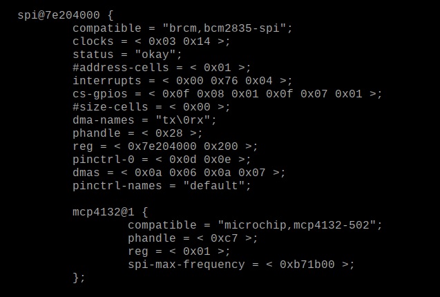
Now, suppose we attach a new SPI device MCP4132-502 to the SPI bus of raspberry pi and CE1as chip select. We can use the ready made driver available in the Raspberry Pi kernel source (https://github.com/raspberrypi/linux/blob/rpi-4.19.y/drivers/iio/potentiometer/mcp4131.c) . This module registers the SPI_driver and informs the kernel about the call back probe() function that need to be invoked whenever there is a device found in the system compatible to this driver. This driver should work as it is on the Pi but how do we inform the kernel about the availability of a compatible device in the system? Because probe( ) function will not be called unless the kernel finds a compatible device. And unless the probe is called, the IIO device will not be exported by the driver making the driver ineffective.
Having the MCP4132-502 device in the system's device tree is the obvious answer but in this case we are attaching the device to a running system and the device (MCP4132) was not there in the system's device tree by default. In this scenario, we need to add the device to the device tree using a DT overlay.
How to write a DT overlay?
The code snippet below is DT overlay for MCP4132-502 which is attached to SPI0 and using chip select 1.
/* example of DT overlay for MCP4132-502 device*/
/dts-v1/;
/plugin/;
/ {
    compatible = "brcm,bcm2835";
    /* the spi config of the can-controller itself binding everything together */
    fragment@0 {
        target = <&spi0>;
        __overlay__ {
            /* needed to avoid dtc warning */
            #address-cells = <1>;
            #size-cells = <0>;
            pot1: mcp4132@1 {
                reg = <1>;
                compatible = "microchip,mcp4132-502";
		spi-max-frequency = <12000000>;
            };
        };
    };
};
Each new node must be defined as fragment in the overlay code. If you want to have more than one nodes to be inserted to DT you have to use fragment@0 fragment@1 and so on. It is mandatory to define the target for the new node. In the code above, the new node is going to be a child node to SPI0. __overlay__ defines the node as overlay.
You must define the required properties of the node in the overlay that you wish the drive to know and act accordingly. In the above node for MCP4132-502, the SPI frequency is defined and chip select is defined as 1. To write DT overlay for any device, you have to follow similar type of scripts and save them as a separate .dts file which need to be compiled to binary .dtbo and be inserted into appropriate location. Location in raspberry pi for overlay binary files is /boot/overlays.
How to compile a DT overlay?
Now, once you have the DT overlay code written into a .dts file, you have to compile it to .dtbo file. Command to compile the .dts file is:
#sudo dtc -@ -I dts -O dtb -o /boot/overlays/mcp4132.dtbo mcp4132.dts
Above commands places the newly created mcp4132.dtbo into /boot/overlays in the raspberry installation. Now we have to activate the overlay by mentioning it in the /boot/config.txt file. Below is a command to do that.
#sudo nano /boot/conffig.txt add “dtoverlay=mcp4132”
Once DT overlay is successfully inserted in the system's DT, reboot the system. You can verify the creation of new node in the DT by running the command # dtc -I fs /sys/firmware/devicetree/base

#KeepExperimenting!


