

B2B GST Credit Available
- Stock: 0 in Stock
- SKU: 26717
- Delivery Time
- Bulk & B2B RFQ
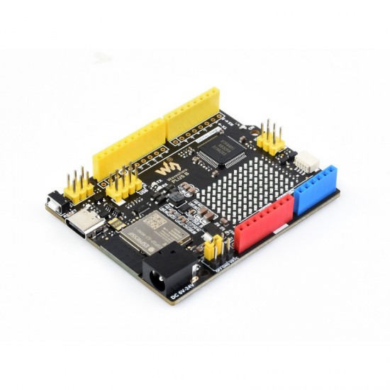
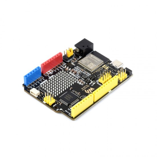
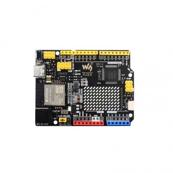
R7FA4 PLUS B Development Board, Based on R7FA4M1AB3CFM, Equipped with ESP32-S3FN8, Compatible with Arduino UNO R4 WiFi
The R7FA4 PLUS B Development Board, Based is on R7FA4M1AB3CFM Chip, R7FA4 Plus B features the ESP32-S3FN8 module, delivering advanced wireless capabilities to the development board. The ESP32-S3FN8 facilitates seamless connectivity, making it ideal for applications that require WiFi functionality. This integration opens up possibilities for IoT projects, remote monitoring, and wireless communication, enhancing the versatility of your designs.
![]() User Manual / Datasheet / Example Codes Etc.
User Manual / Datasheet / Example Codes Etc.
Specifications
- MICROCONTROLLER : R7FA4 (32-bit ARM Cortex-M4) / ESP32-S3FN8 (Dual-core 32-bit Xtensa LX7)
- CLOCK FREQUENCY : R7FA4: 48MH / ESP32-S3FN8: 240MHz
- STORAGE : R7FA4: 256kB Flash, 32kB RAM / ESP32-S3FN8: 384kB ROM, 512kB RAM, 8MB Flash
- WIRELESS COMMUNICATION : 2.4GHz WiFi + Bluetooth LE
- OPERATING VOLTAGE : Options for 5V/3.3V, support more shields
- POWER INPUT : 6~24V
- RESET BUTTON : Lateral, easier to use when connecting with shield
- DC JACK : Low profile, shields won't be blocked anymore while connecting
- POWER OUTPUT HEADER : Provides 5V OR 3.3V power output and common-grounding with other boards
- 5V POWER OUTPUT : Up to 2000mA Max, features higher driving capability
- EXPERIMENTAL BOARD : Support, solder pad is provided for DIY interfaces to connect with experimental board
- IO PIN OUTPUT CURRENT : 8mA
- DIGITAL PINS : 14
- ANALOG PINS : 6
- DAC : 2
- PWM : 6
- UART : 1
- I2C : 1
- SPI : 1
- CAN : 1
Package Includes
- R7FA4 PLUS B x1
- USB Type-A to Type-C cable x1
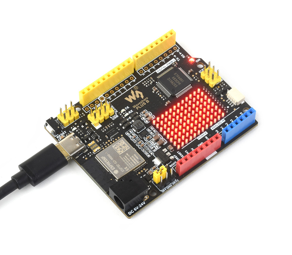
Onboard 12×8 Red LED Matrix
What's On Board
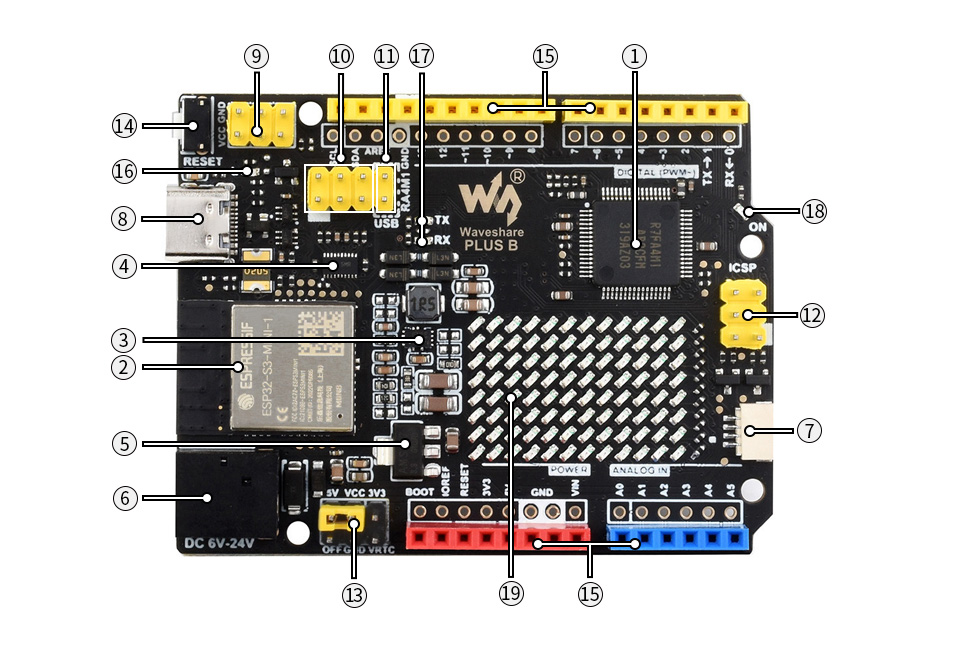
1. R7FA4M1AB3CFM
2. ESP32-S3-MINI-1 module
3. MP8759
- 5V voltage regulator
4. TXB0108DQSR
- voltage translator, for communication between R7FA4 and ESP32-S3
5. AMS1117-3.3
- 3.3V voltage regulator
6. DC input
- 6V ~ 24V
7. Qwiic connector
- for connecting I2C device of Qwiic Eco
8. USB Type-C connector
- for uploading program OR serial port debugging
9. Power output header
- 3.3V OR 5V, voltage level configured by the onboard power configuration switch, used as power output and common-grounding with other boards
10. ESP32-S3 pinheader
- for ESP32-S3-MINI-1 firmware downloading
11. USB communication selection
12. ICSP interface
13. Power configuration
- for configuring R7FA4 PLUS B operating voltage
14. Reset button
15. Arduino interface
- compatible with standard Arduino interface, adapting 2.54 pitch solder pad, can be directly connected to experimental board
16. User LED
17. Serial port RX/TX indicators
18. Power indicator
19. 12×8 LED matrix
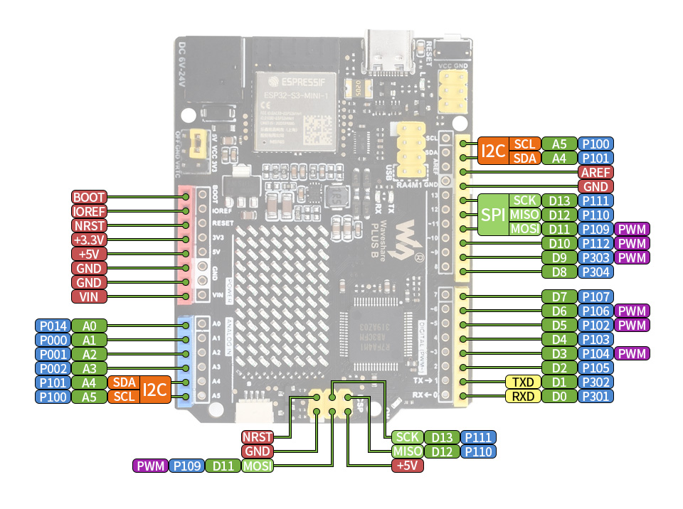
Pinout Definition
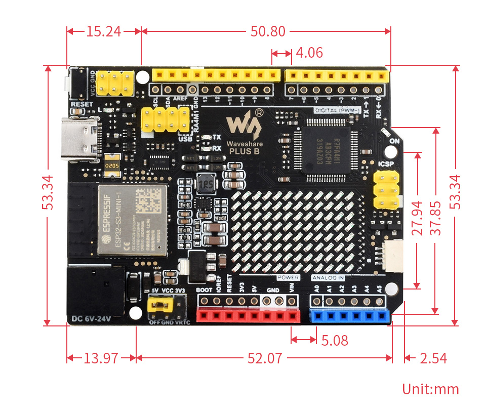
Dimensions
