
Wiring it Up

To get started type in the terminal ---> man gpio
This will brief you on the various commands available via command line to control the GPIO pins.
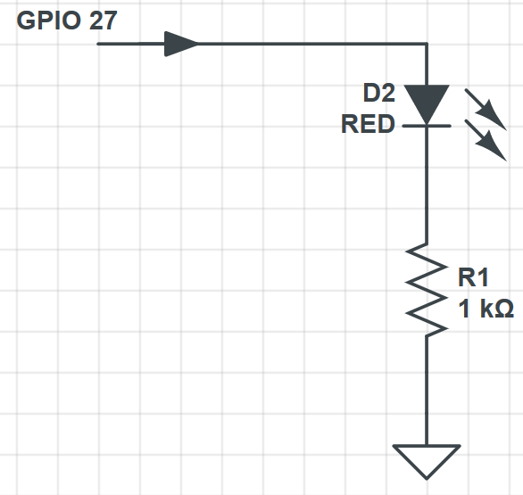
Next, we need to choose a pin that we will control with our char driver. Chose any PIN labelled GPIO (exclusively) from the figure above (let’s take GPIO 27 for this example). Connect that to the Anode of the LED.
Connect the Cathode of the LED to a 1KOhm resistor (for current limiting/safety) and the other end of the resistor to GND.
Once that is done enter the command
---> gpio readall

The red box gives a 1-1 representation of your actual header configuration. Since you had connected the led to pin 13 you can now see that the BCM index of that pin is 13 and its internal name is in fact GPIO 2 (this is not important for our work).
Try the command ---> gpio -g write 27 1 && gpio readall
This should set GPIO 27 and you can verify that as your LED will now glow and you will be able to see 1 in the “V” column in the output table.
Feel free to experiment with the other commands available via command line.
Char Driver Component
Using a basic skeleton char driver we will implement the functions to set and clear the GPIO pin using the file_operations constructor. Ergo, the read callback will set the pin and the write callback will clear it.
To be able to use the GPIO functionality of the RPI in kernel space we cannot simply import wiringPi.h and use its functions and defines.
Instead we will have to manually address the GPIO function handling registers present in the RPi’s memory.
To accomplish this we start by getting the RPi’s Broadcomm processor’s datasheet. For RPi Model 4B it’s the BCM2711. Datasheet here. Datasheet for 3B+ here. Peripheral mapping is the same for both.
Run the following command ---> sudo cat /proc/iomem
This gives you the address mapping of all the peripherals supported by the SoC. Find GPIO in this list and note the address.
Then go through the RPi 3B+ datasheet to figure out the register offsets for the pin mode, pin set and pin clear GPIO registers. Note those down.
IOREMAP Function
This function is used to access physical memory through the virtual page table my re-mapping the physical address to one in the Page table. So, when we need to access that memory, the OS’s memory management can directly access that location without the need for any kernel hacking, and any read/writes will be automatically synced between the RAM and the mapped register.
SYNTAX:
void *ioremap(unsigned long phys_addr, unsigned long size);
void iounmap(void * addr);
#define PERIPH_BASE 0x3F000000
#define GPIO_BASE (PERIPH_BASE + 0x200000)
uint32_t read_reg_val,write_reg_val;
static uint32_t* sel_reg;
if ((sel_reg = ioremap(GPIO_BASE+0x08,0X04))==NULL)
{
printk(KERN_INFO "IOREMAP FAIL");
return -1;
}
/** now any read/write to the pointer sel_reg will be synced with the peripheral control register **/
read_reg_val=readl(sel_reg); //how to read
write_reg_val= (0xFF3FFFFF&read_reg_val)|0x00200000; //how to mask and write
TASK
Using the file_operations constructor, setup a char driver to make toggle an LED on if the device is read from and toggle off if the device is written to.
TIP: Download and install WinSCP for file transfer between the RPi and your system. If it does not work from the VNC Viewer Interface.
Related Products
 for Raspberry Pi, 320×240, SPI")
, 1024×600, HDMI, IPS, Low Power")
